Infrared thermopile CO2 sensor STG-EA12-CD
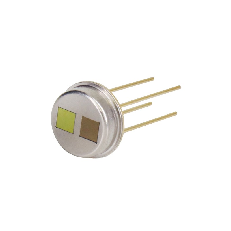
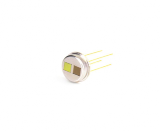
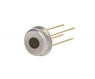
STG-EA12-CD Infrared thermopile gas sensor can measure the CO2 gas concentration through the change of the resistance value of the internal thermistor. The product is packaged in a TO-39 metal socket and has two separate filters: one is the reference filter and the other is a narrow bandpass filter for the CO2 gas band. The sensor integrates electronic components such as thermopile chips and thermistor, with high reliability and high sensitivity.
Key information:
TO-39 Package
High Sensitivity
NTC Thermistor Compensation
Fast Response
4.26μm, 3.91μm Narrowband Filter
Technical data:
Parameter | Min. | Typ. | Max. | Units | Test condition |
Chip size | 1.6×1.6 | mm2 | |||
Sensitive area | 1.1×1.1 | mm2 | |||
Thermopile resistance | 95 | 120 | 140 | KΩ | Temp=25℃ |
Noise voltage | 45 | nV/Hz1/2 | Temp=25℃ | ||
NEP | 0.27 | nW/Hz1/2 | Blackbody=500k, 1Hz@25℃ | ||
Responsivity | 124 | V/w | Blackbody=500k, 1Hz@25℃ | ||
Temp. Coefficient of resistance | 0.1 | %/℃ | Temp=25℃~75℃ | ||
Time constant | 10 | ms | |||
Specific detectivity | 1.0E+08 | cmHz1/2/w | Blackbody=500k, 1Hz@25℃ | ||
NTC Resistance | 100±3% | KΩ | 25℃ | ||
NTC β | 3950±1% | K | 25/50℃ | ||
Environmental requirement | |
Working temp. | -30℃~+85℃ |
Storage temp. | -30℃~+100℃ |
Spectral curve:
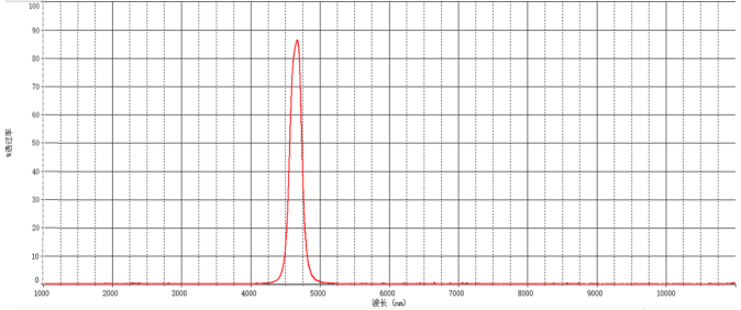
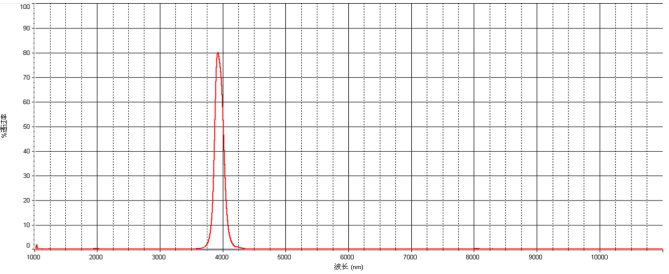
Dimensions (unit: mm):
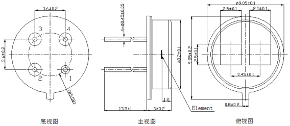
1.GND | 2. NTC | 3.TP2 | 4. TP1 |
Cautions:
1. Design Limitations
This sensor is designed for indoor use.
When used for outdoor applications, be sure to use a suitable supplemental optical filter and moisture-proof construction.
To avoid secondary failures due to operational failures or malfunctions, a fail-safe function can be added in advance.
2. Restrictions on Use
To prevent sensor malfunction, operational malfunction, or any other malfunction, do not use this sensor under the following or similar conditions.
(1) Dramatic changes in ambient temperature.
(2) Strong vibration or shock.
(3) Infrared rays cannot pass through the detection area when passing through a place with a barrier material (glass, fog, etc.).
(4) In liquids, corrosive gases and seawater.
(5) Continuous use in high humidity atmospheres.
(6) Static electric field or strong electromagnetic wave radiation.
(7) Corrosive gases or sea breeze.
(8) Dirty and dusty environment that may contaminate the optical window.
3. Soldering restrictions
(1) Soldering with a soldering iron. Soldering temperature at 260 ℃ within 10 seconds. Avoid keeping the sensor pins overheated for a long time.
(2) After soldering, all flux must be cleaned off and rinsed with a brush. Using an ultrasonic cleaner may cause performance failure.
4. Product Use Restrictions
Use and sell subject to any applicable laws or regulations.
Sensor failure due to misuse, improper handling or storage is not the responsibility of the manufacturer.
Inquiry
Product
CATALOGUE
 angela